Over time, continuous field use, mechanical stress, and environmental exposure can degrade sensor performance, making it essential for technicians to understand how to test a metal detector coil accurately. Mastering systematic coil testing procedures ensures that security checkpoints remain fully compliant, highly responsive, and immune to unexpected hardware failures.
What is a metal detector coil and why does it matter?
A metal detector coil is the sensing component that interacts with the electromagnetic field around the detection area. Its condition can directly affect detection performance and system stability.
To properly diagnose and maintain screening infrastructure, security personnel must first comprehend the foundational role of the search head within the wider detection circuit. A metal detector coil functions as the primary electromagnetic transducer, converting electrical energy into active magnetic flux fields and capturing secondary voltage perturbations induced by nearby conductive objects.
Whether integrated into the multi-zone side panels of a walkthrough inspection portal or housed within the compact probe tip of a hand-held security wand, the coil establishes the operational boundary of the entire system.
Its physical and electrical condition directly governs the sensitivity, spatial resolution, and false alarm rate of the device. If the winding geometry is compromised, internal insulation degrades, or minor microphonic shifts occur within the housing, the system’s null balance and electromagnetic response will instantly suffer.
Consequently, monitoring the health of this critical component through structured diagnostics is not merely a maintenance routine; it is an absolute operational necessity to guarantee that prohibited metallic contraband, weapons, and security threats are intercepted without exception.
How to test a metal detector coil
When maintenance technicians or security operators encounter erratic behavior, baseline drift, or unexpected false alarms in screening equipment, executing a systematic diagnostic protocol is essential. Knowing how to test a metal detector coil involves a structured sequence of physical, visual, and electrical checks designed to isolate faults and verify component integrity before deploying equipment into active service lanes. Below is the step-by-step diagnostic workflow required to thoroughly evaluate a metal detector search head.

Step 1: Check the coil and housing visually
The initial diagnostic phase begins with a meticulous physical inspection of the exterior housing and structural potting compound. Technicians must examine the entire surface of the search head for cracks, deep abrasions, punctures, or signs of impact damage that could allow moisture, dust, or conductive debris to penetrate the interior enclosure.
Any compromised structural integrity on the outer shell frequently indicates internal wire displacement or stress fracture, which will inevitably cause erratic electrical behavior and nuisance alarms during active screening operations.
Step 2: Inspect the coil cable and connectors
Following the exterior shell review, attention must shift to the interconnecting cables, strain reliefs, and connector pins. Cable assemblies are subjected to continuous mechanical flexures, tension, and environmental wear-particularly in portable hand-held units or deployable screening setups.
Technicians should inspect the cable jacket for cuts, kinks, or exposed shielding, and verify that connector plugs are free of corrosion, bent pins, or loose locking collars. A compromised cable shield or intermittent wire connection within the harness will introduce severe ambient noise and signal dropout. (1)
Step 3: Check electrical continuity when applicable
To verify the internal electrical health of the inductive windings, technicians utilize precision diagnostic tools to measure circuit pathways. When permitted by manufacturer specifications, checking electrical continuity helps confirm that the conductive wire loops are intact and free of internal open circuits.
This step requires isolating the coil from sensitive control electronics to prevent accidental voltage feedback, ensuring that the DC resistance across the designated terminals falls within expected baseline parameters.
Step 4: Compare measurements with manufacturer specifications
Raw electrical measurements are meaningless without a benchmark. Once resistance and inductance values are captured using calibrated multimeters or specialized LCR meters, technicians must compare these figures directly against the official factory datasheets or service manuals provided by the equipment manufacturer.
Significant deviations-such as abnormally high resistance indicating a degrading winding, or lowered inductance suggesting a shortened turn-confirm that the coil has suffered internal failure and requires immediate replacement or factory servicing.
Step 5: Test the detector using a known reference target
After verifying electrical and physical health, the search head must undergo a functional live-fire test utilizing standardized reference items. Technicians pass approved test objects-such as standard test pieces, calibration blocks, or controlled metallic contraband samples-through the active detection zone at standard velocities and orientations.
This functional verification ensures that the system’s sensitivity gradients, phase-discrimination circuits, and multi-zone alarm thresholds respond correctly and consistently to target inputs.
Step 6: Check for intermittent performance
The final diagnostic verification addresses thermal and mechanical stability under operational conditions. Technicians gently flex the coil cable, tap lightly on the housing enclosure while monitoring the control panel, and observe baseline performance over an extended testing window.
This step uncovers latent manufacturing defects, cold solder joints, or intermittent internal shorts that only manifest when the hardware is subjected to physical vibration, handling movement, or ambient temperature fluctuations in active security environments.
What can cause a metal detector coil to fail?
When diagnostic routines reveal a drop in detection efficiency, erratic baseline signals, or complete system failure, identifying the root cause requires evaluating the environmental, mechanical, and electrical stresses placed upon the sensor. A metal detector coil is subjected to continuous operational pressures, and several distinct failure mechanisms can compromise its structural and electrical integrity over time:
- Physical damage to the coil: Exterior impacts, heavy handling drops, or sharp abrasions can crack the protective polymer housing, allowing moisture or external contaminants to seep directly into the winding enclosure.
- Damaged or loose wiring: Continuous mechanical flexure, vibration during transport, or improper cable strain relief can fatigue internal copper conductors, leading to intermittent connections or complete open circuits.
- Connector problems: Corroded contact pins, bent terminal prongs, or loose locking rings on the signal cable assembly introduce high contact resistance and disrupt signal transfer between the coil and the control unit.
- Moisture and environmental exposure: Ingress of humidity, rain, or cleaning fluids into micro-cracks causes capacitive coupling shifts and dielectric breakdown, triggering constant baseline drift and false alarms.
- Electrical faults: Shorted turns within the winding loops-often caused by thermal stress or insulation breakdown-drastically alter the inductance and resistance values, distorting the electromagnetic balance.
- Long-term wear and mechanical stress: Years of physical deployment, temperature extremes, and repeated thermal expansion/contraction cycles cause the internal epoxy potting compound to fatigue, allowing microphonic wire movement.
Read more: Metal detector DD coil.
How to know if a metal detector coil is working properly
A metal detector coil is working properly when it produces a stable electromagnetic response, maintains consistent sensitivity across its entire scanning area, exhibits no unexplained alarms, shows no visible physical damage, and yields electrical measurements that align precisely with manufacturer specifications.
Verifying that a search head is functioning within optimal operational parameters is essential before deploying screening equipment to active checkpoints. Technicians and security managers look for specific behavioral and measurable indicators to confirm peak hardware health.
1. Stable detection response
A properly functioning coil maintains a rock-solid baseline electromagnetic field without drifting, oscillating, or generating random noise when stationary. It responds smoothly and predictably only when a metallic target enters its active inspection zone, ensuring that the control unit receives clean, undistorted analog signals.
2. Consistent sensitivity
Uniformity is a hallmark of a healthy sensor assembly. Whether a test object is passed through the upper, center, or lower sections of a walk-through portal or swept across various points of a handheld wand, the device must register the target with identical amplitude and reliability, indicating no dead zones or degraded coil turns.
3. No unexplained alarms
False or nuisance alarms that occur without any moving metal objects or environmental interference nearby often point to internal coil instability, shielding breakdown, or loose wiring. A fully operational unit remains completely quiet and stable until a genuine threat object crosses its inspection path.
4. No visible physical damage
An exterior structural check must reveal an intact, uncracked housing, secure mounting hardware, and an unblemished cable jacket. The absence of physical wear ensures that internal windings remain hermetically sealed and protected against external elements.
5. Electrical measurements within specification
When evaluated using diagnostic instruments, the coil’s measured DC resistance, inductance values, and insulation resistance must match the exact engineering tolerances outlined in the official technical documentation provided by ProScan Global.
How to test a metal detector coil with a multimeter
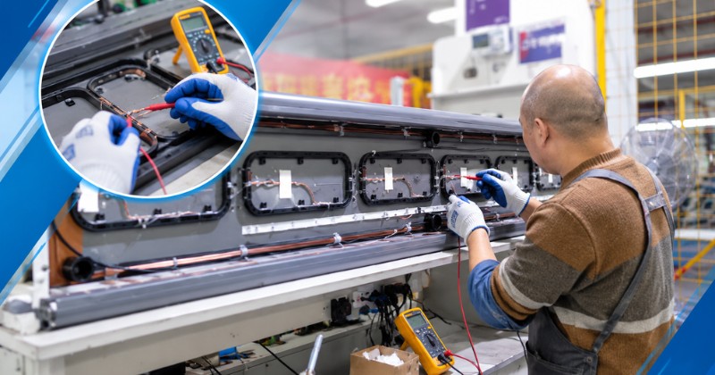
Testing a metal detector coil using a digital multimeter is a fundamental diagnostic procedure used by maintenance technicians to isolate electrical faults, verify winding continuity, and check for internal short circuits. Because search coils rely on precise electrical characteristics, utilizing a multimeter requires strict adherence to proper testing protocols to avoid damaging sensitive control electronics.
Before beginning, technicians must ensure that the metal detector is completely powered off and disconnected from any power source or control unit. If the coil features an integrated cable, the connector pins must be safely accessed. The multimeter should be set to the lowest resistance (Ω) scale for continuity and winding resistance checks, or to an inductance measurement mode if using an advanced LCR meter.
First, test for electrical continuity across the primary terminal pins corresponding to the coil’s winding circuit. A continuous low-resistance reading confirms that the copper wire path is unbroken. If the multimeter displays an “OL” (open loop) or infinite resistance, it indicates a broken internal wire or open circuit within the coil assembly.
Next, check for short-to-ground faults by placing one multimeter probe on the connector’s metal shielding or outer housing and the other probe on the active signal pins. A proper coil should show infinite resistance (no connection) between the signal wires and the shield; any low-resistance reading reveals a short circuit caused by moisture ingress or insulation failure.
Finally, compare the measured DC resistance value against the official factory specifications. If the resistance is significantly lower than specified, it indicates shortened turns within the winding, whereas a much higher reading points to corroded internal connections or a severely degraded conductor.
What should you do if a metal detector coil fails the test?
When diagnostic evaluations, visual inspections, or multimeter measurements confirm that a metal detector coil has failed, immediate corrective action must be taken to maintain facility security and prevent compromised screening integrity. Operating defective security equipment leaves checkpoints vulnerable to undetected threats and creates unacceptable compliance risks.
The first and most critical step is to immediately take the affected screening device-whether a walk-through portal or a hand-held unit-out of active service and tag it out for maintenance. Attempting unauthorized field repairs, such as splicing damaged cables improperly or attempting to open sealed epoxy coil housings, should be strictly avoided, as this will permanently invalidate equipment warranties and introduce safety hazards.
Facility managers should consult directly with ProScan Global’s technical support team to secure certified OEM replacement components or arrange professional factory servicing. Utilizing genuine, factory-tested replacement coils ensures that electrical parameters, inductance ratings, and impedance matching remain perfectly aligned with the control unit, restoring the security checkpoint to peak operational performance swiftly and reliably.
Why ProScan provides reliable metal detection solutions
As an established global leader in the intelligent security inspection industry, ProScan delivers comprehensive, cutting-edge security solutions to municipal governments, aviation hubs, correctional facilities, and major public events across more than 100 countries.
Backed by advanced research and development facilities alongside automated production bases, ProScan Global specializes in a robust product ecosystem that includes high-performance walk-through metal detectors, precision hand-held metal detectors, advanced shoe scanners, and comprehensive Under Vehicle Surveillance Systems (UVSS).
ProScan Global’s unyielding commitment to engineering excellence, rigorous quality control, and international safety standards sets the industry benchmark. Every security inspection system is designed in strict compliance with international electromagnetic compatibility (EMC) and electrical safety benchmarks, utilizing weak magnetic field technology that guarantees complete safety for pregnant women, children, and pacemaker wearers.
FAQs about testing metal detector coils
1. How do you test metal detector coil continuity?
Testing metal detector coil continuity involves using a digital multimeter set to its lowest resistance (Ω) or continuity beep mode to verify that the internal copper wire windings are unbroken and forming a complete electrical circuit. After safely disconnecting the coil from the control unit to prevent electrical feedback, technicians place the multimeter probes across the designated terminal pins of the connector.
A continuous, low-resistance reading that matches the manufacturer’s specified baseline indicates that the winding circuit is healthy. Conversely, an infinite resistance reading (“OL”) signifies a broken wire or open circuit within the sensor assembly, requiring repair or replacement.
2. Can a multimeter test a metal detector coil?
Yes, a standard digital multimeter is an essential diagnostic tool that can effectively test several key parameters of a metal detector coil, including electrical continuity, DC resistance, and short-to-ground faults. By measuring resistance across the terminal pins and comparing the results against factory specifications, technicians can quickly identify open circuits, corroded connections, or shorted winding turns.
However, standard multimeters cannot measure inductance or complex impedance accurately; evaluating those advanced electrical parameters requires specialized LCR meters or dedicated factory diagnostic test fixtures provided by certified manufacturers like ProScan Global.
In summary, maintaining the operational readiness of modern security inspection infrastructure requires a proactive approach to hardware diagnostics and component maintenance. Throughout this comprehensive guide, we have examined how to test a metal detector coil systematically, exploring vital visual inspections, electrical continuity checks, multimeter diagnostics, and performance verification protocols.